Technical Matters
Fixed Steel Ladder Construction
Preamble
What is outlined on this page is the way I made the fixed ladder for the Home Close dig. I do not claim that this is the only way, the best way or the easiest way; but it did end up producing straight ladders that fitted together without a lot of problems.
The design
The term "design" for the process described here is rather pretentious, because it was a cobbling together of what was most easily available, but we have "designer jeans" for goodness sake, so what the hell.
The ladder was constructed using imperial measurements (feet and inches) for a number of reasons, apart from sheer bloody-mindedness, although that did come into it to a certain extent.
Firstly, the steel stockist I used sells steel strip in 20 ft lengths, nominally 6.1 metres. These are too long to use uncut but they divide nicely into two for the side rails. Secondly, a half section of this ladder (5 ft) is an ideal length to tack onto the bottom as an intermediate measure before a full 10 ft section is added. Thirdly, Mendip caving ladder has traditionally had a 10 inch rung spacing, I am used to climbing ladders with this spacing and 12 rungs with 10 inch spacing fits into 120 inch lengths of side rail. Case closed.
The width of the rungs was decided on by donning a pair of wellie boots, standing comfortably and then marking left and right. This advanced ergonomic technique indicated a rung width of a shade under 10½ inches (actually 10.4") between the side rails.
Construction
Jigs
Having completed the design stage, various jigs were made up to help with the construction. The primary jig (numbered 1 in Figure 1.) was a 16 inch length of 40 × 8 strip drilled centrally with 3/16" holes at 1, 4, 5 and 15 inches. This defined the end of the ladder, boltholes for the fish-plate connector and the first and second rungs. This jig was then laid on a 10 ft length of strip and the measurements transferred by punching down with a 3/16" diameter punch (made out of a pointed drill stub - see Figures 2 & 3) as the primary jig was walked up the 10 ft strip. The 10 ft strip was then drilled with 3/16" holes and this became the jig for marking the ladder side rails and was preserved carefully thereafter.
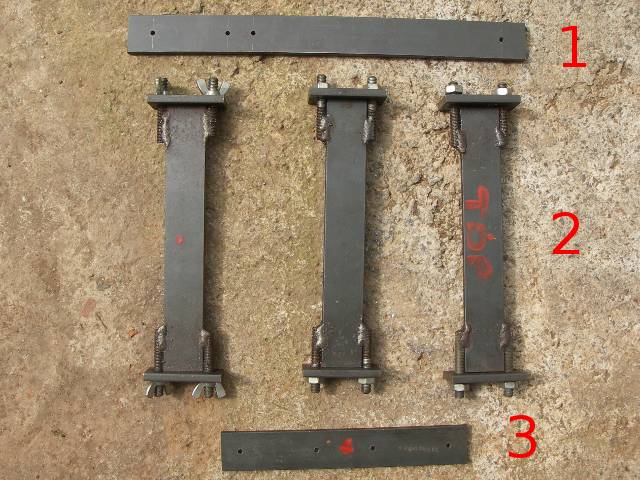 Fig 1: Ladder making jigs |
 Fig 2: The 3/16" punch |
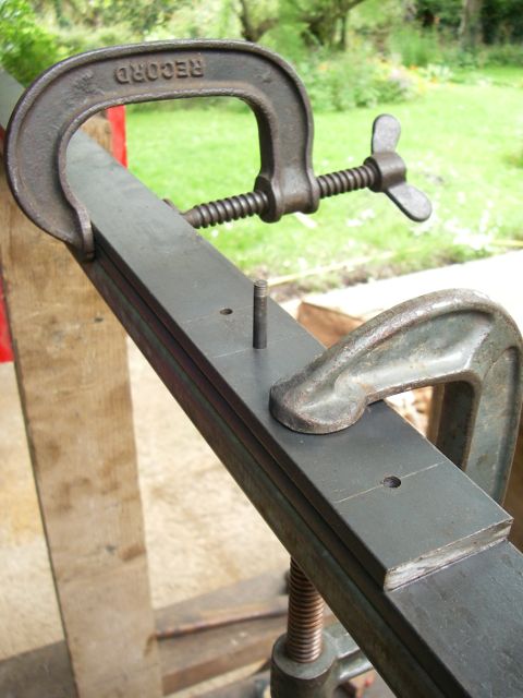 Fig 3: The punch in position |
Three spacer jigs to hold the side rails were made up (numbered 2 in Figure 1). One of these was fixed at the bottom of a ladder section, the positioning of the other two is described in the Drilling and welding section below.
Finally, a jig was made up to aid the drilling of the fish-plates to join two ladder sections (numbered 3 in Figure 1).
Drilling and welding.

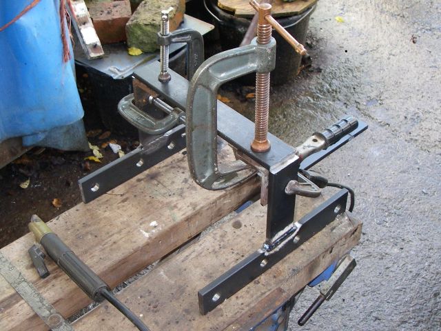
Before drilling the ladder side rails, it is necessary to set up some sort of support system. This needs to extend for 10 feet on either side of the machine vice of the pillar drill. I used a couple of lengths of lightweight perforated channel sections joined by a bit of force-fit ply, see Figure 4. As luck would have it, the machine-vice gripped the ladder rail tightly while just gripping the perforated channel; sometimes these things just happen, but not often.
When making a 10 foot length of ladder, two rails would be drilled with ½ inch holes at the same time, stacked one above the other. However you may have noticed that the photograph shows only one rail being drilled. This was to make a single 5 foot length of ladder, a single side rail being drilled which was them cut in half.

After drilling, two side rails are set up on a levelled block of wood and clamped together with two spacing jigs, one clamp at the bottom and the other about 6 ft higher. While not strictly relevant, the "Black Shed", where all this is going on, has an angle-iron door frame, the top of which which is very useful when it comes to clamping spacing jigs and the like and holding them firmly. However, the exact method is irrelevant, it is just necessary to hold the top jig firmly in position. Now previously, these two jigs had their mid points marked with file cuts, so a plumb line could be used to ensure verticality. It is important to get this right.
Having set up the side rails as described, the pre-cut rungs are fitted in and then one-by-one clamped and tack-welded to the inside edges of the rails. The ladder is then turned upside down and the remaining rungs clamped and tack-welded.
Regarding the welding, I found it easier firstly just to tack the rungs to the insides of the side-rails and then to lay the ladder on its side and do a downhand weld around the end of the rung to attatch it to the side rail
When making the first three lengths of ladder back in 2008, I cut the rungs more or less flush with the outside edge of the side rails. Hindsight has shown that it is better to cut the rungs just a little longer and I now use 12mm washers fitted over the protruding ends of the rungs as a gauge and also when clamping the rungs. This extra length makes the welding of the rung to the outside of the side rail much easier.
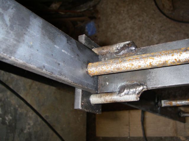
Finally, units consisting of a cunning combination of fish-plate connectors, ladder stand-offs and supports are drilled and welded up as illustrated in Fig 7.
The fish plates are drilled with four ½ inch holes in each side to take the 12mm connecting bolts. They are welded to 4 inch deep standoffs, which are in turn welded to a backplate, drilled with a central hole, allowing the assembly to be bolted to the concrete pipe, the rock or anything else that comes handy.
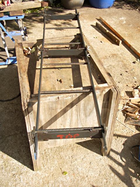
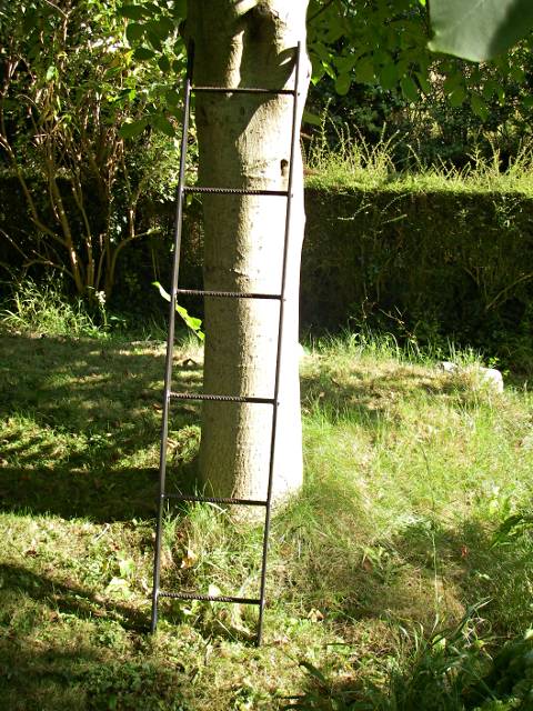
Figure 8 shows a 5 ft length of ladder tacked and ready for welding. This particular ladder uses 12mm re-bar for the rungs. Now a heap of off-cuts of re-bar were delivered by the re-bar fairy and therefore they were a good thing to use, but 12mm re-bar requires more preparation before it is a good fit. Round bar is easier but much more expensive.
Figure 9 shows a completed section of ladder.
Materials
- Mild steel flat 40 × 8mm for the side rails. (Avon Steel Company Ltd.)
- Mild steel round 12 mm diameter bar for the rungs. (Avon Steel company Ltd.)
- 12 mm re-bar was also used as rung material 'cos it was going cheep, but it does require more preparation.
- M12 bolts, washers and nuts (Various sources).
 |
 |
Created: Wed Jul 27 19:24:51 2011
Revised: