Technical Matters
The Telephone System
The rationale
I have been involved with several types of digging telephones in various digs over the years. While a few have worked well in the short term, none has worked satisfactorily over the long term. They just do not seem to be able to tolerate wet mud. Strange.
It seemed that some alternative method ought to be be adopted and it occurred to me that it would be worth trying to use easily replaceable standard domestic components and swap the phones as they they are about to fail. It has been my experience that underground phones rarely failed suddenly and completely, but that usually speech gradually became more and more unintelligible. In other words, there was usually some warning of impending failure.
The speech part of a standard phone system is no problem, it takes a matter of minutes to rig up an intercom using two instruments, two wires and a battery wired in parallel. The difficulty is signalling to the other end that you need to talk to them. Phones connected to the public network use two wires and run on a 48 volt central battery for the speech element, but require 80 volts AC at 20 Hz (used to be 16.67 Hz in UK) to ring the signal bell (or electronic gizmo in a modern phone). It is obviously possible to generate this signal, but it ends up a bit complicated. One could, of course, use another two wires, together with batteries, push buttons and bells to form a signalling circuit, but that would be a messy and totally unworthy solution.
A search on the dreaded interweblet turned up a simple and rather elegant solution to the problem. Markus Wandel (website wandel.ca) had in 1993 published on Usenet a neat circuit which solved the problem. I thank Markus for giving his permission for it to be displayed here. (Fig 1 below).
The circuit
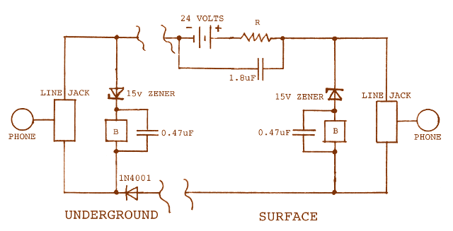
Components
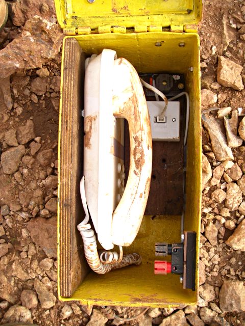
Underground - (mounted in ammunition box)
- Zener diode BZT 03C15 (RS 7087-849)
- Buzzer (B) Sonitron SMAI-24A5P10 (RS 172-7560)
- Capacitor 0.47 μF - plastic film
- Diode (I used a 1N4001 but the type is not critical)
- Line Jack Secondary IDC Line Jack Unit LJU1/3A (RS 470-358)
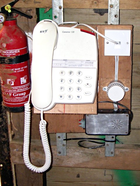
- Telephone A standard BT Converse 120 unit (scrounged).
Surface - (Mounted on board)
- Zener diode BZT 03C15 (RS 7087-849)
- Buzzer (B) Acoustic Signals AE35M02 (RS 249-788)
- Capacitor 0.47 μF - plastic film
- Capacitor 1.8 μF - plastic film
- Resistor (R) 110 Ω - [see note below]
- Line Jack Secondary IDC Line Jack Unit2/3A (RS 470-370)
- Telephone A standard BT Converse 120 unit (scrounged).
Notes:
- Resistor R is chosen so that the current flow with both phones off-hook is about 25mA, I actually used two 220 Ω resistors in parallel.
- The phone line needs to be connected the right way round and the 1N4001 diode in the underground set is to prevent current flow if it isn't. (This is my only alteration to Markus' design).
- The 1.8 μF capacitor shunts the voice signal round the battery and resistor, the 0.47 μF caps increase the feedback from the buzzers and create the illusion of a dial tone.
- Sonitron sounders were originally used at both ends, but the surface sounder could not be heard over the winch engine so it was replaced by one WHICH COULD.
- The telephone line is connected to line jack terminals 2 (-ve) and 5 (+ve)
- The numbers in brackets are RadioSpares part numbers (or 'R.S Components' part numbers if you must be up to date).
Operation
The circuit is slightly unusual in that the battery is in series with the two phones, rather than parallel, but it works none the less. When both phones are on hook, no current flows through the phones and the zener diodes block 15 volts each, i.e a total of 30 volts, so no current flows through the buzzers either. When one phone is lifted off-hook, the low resistance of the phone effectively shorts out the zener at that end and 24 volts is applied to the zener/ buzzer combination at the other end. The other zener removes 15 volts, leaving 9 to activate the buzzer, which sounds - squeeeeek!. When the second handset is picked off-hook, current now flows through the two phones, the buzzer stops and a sensible conversation can take place. (Perhaps that is going a bit far).
(A better photograph of the underground end will appear when I have taken it).
Slight modification - August 2013
In use, the underground handset came off hook very easily when it was knocked as diggers crawled past it. Unlike the weighty handset of the good old GPO type 332 instrument, the effete 'Converse 120' handset is a mere feather-weight and bounces off hook at the slightest jolt. However opening the handset and stuffing it with as much lead strip as possible has given it a bit more gravitas and now when it is put down, it stays down.
 |
 |
Created:Tue Mar 20 18:27:43 2012
Revised: