Technical Matters - The Shaft
Preamble
Home Close Hole started as a rather a rather problematical and technically challenging dig and it took over three years of concentrated effort to get to the point when actual digging could begin.
Various explanations for this have appeared in the digging log but they are scattered and perhaps not that easy to understand. This page is an attempt to bring most of the details about the shaft and its attendant problems into one place. As such it does repeat some of the log material, but hopefully offers a more coherent and understandable explanation.
The starting position and possibilities
Back in August 2008, after the great open pit had been backfilled, we were left with a 10 metre stack of concrete pipes. These were sitting on, and surrounded by, a mixture of mud and stone and were sited somewhat less than a metre from a solid rock wall on the north and rather closer to more rock to the west. Initially, the fill surrounding the bottom of the shaft was sufficiently wet to be almost free-flowing.
If the site were ever going to be dug, then the first job was to find some way of hanging on to what we aleady had. The shaft would have to be stabilised, ideally by keying it somehow to the solid rock of the rift. Beyond that, three possibilities were considered; firstly to tunnel south to the southern wall of the rift, cast a BIG beam then dig on down, in a similar manner to the first dig at Charterhouse Warren. This was a silly option and if it had worked, which I think unlikely, it would have been extremely slow.
Considering that the open passage below was some 100 metres down and the eastern end of the rift maybe only 8 to 10 metres away, the possibility of gradually tunnelling under and roofing over the rift then totally excavating it was BRIEFLY considered. This was my idea and even I thought that it was stupid. But wouldn't it have been a FANTASTIC entrance shaft?
The third possibility considered was to work from the bottom of the shaft to the west and get into the narrow continuation rift-like feature that was seen in August 2008.
If this could be entered and the further reaches enlarged then we could create an 'hour-glass' or figure '8' like feature which would mean that we would only have to consider shoring the waist region of the hour glass. This was a much better proposition, and the one that we adopted. In the event, the cave was kind to us and provided ready made passages for us to enlarge.
For more details of the third option and the rift-like feature at the western end of the site see:-
The Problems
In a nutshell:-
- Wonky shaft.
- No firm foundation to the shaft.
- Very wet and semi-fluid fill.
- Need to tunnel under the fill.
The Solutions
1: Water
The water problem was dealt with by draining surface water down the inside of the shaft to below the level of the concrete. This was very important but the saga has been dealt with ad nauseam in the digging accounts and is sufficiently straightforward not to require further detailed explanation. See the digging log entries for July/August 2009 and May to September 2010 if you want more. The important bit is that the drainage works did dry the fill and make it more manageable.
2: Shaft stability
The initial attempt at stabilizing the rather wobbly pile of concrete rings was the installation of three steel straps, hooked at the top and bottom of the pipes. Each strap was tensioned with a 5 tonne screw jack. At the very least, this held the column of rings together and prevented any particular ring from wandering off on its own.
Having tied the rings together, we had what in effect was a ten tonne pastry cutter with quite a sharp cutting edge, so it was necessary to fit some concrete underpinning to form a sort of 'Elephant's Foot' foundation. If some of this foot could be tied into the solid rock walls of the rift then so much the better. However, in order to stuff in some underpinning, it was first necessary to tunnel out from under the concrete rings. Problem.
During initial attempts at excavating under the rings it was found impossible to hold the wet fill material in place and it collapsed from the top and sides of the excavations. All such collapses generated void spaces behind the concrete rings and thus unbalanced the forces acting on the rings. This was not considered to be a GOOD THING.
3: Underpinning the shaft
This was tackled on two fronts. Although neither of these was sufficient in itself, the combination of the two proved effective. Firstly, the site was drained as mentioned above and then the immediate area of the shaft was capped with a concrete apron which was integrated into the drainage system. Secondly, in order to get concrete under the shaft without triggering more collapses, we needed to be able to dig under the concrete ring, support the excavation as rapidly and effectively as possible and then set up shuttering to allow the void to be filled with concrete. In other words, a rapid acting shuttering/shoring device was required. It seemed a good idea to make up a device that would underpin the shaft using eight concrete segments segments. An alternative would have been to use pre-cast concrete segments, but I felt that this was beyond my technical expertise.
4: The jig and shutter
The combi jig and shutter was a steel framework which could be propped against the inside wall of the concrete shaft and braced against the opposite wall by a single acrow prop. The purpose of this device was threefold:-
- To act as support for long rods drilled into the rock wall, or if necessary, for rods just hammered through the fill in the absence of a rock wall. The fill could then be dug out from below these rods, which acted as temporary support for the stuff above.
- Once the excavation was complete, built-in angle iron legs could be extended down from the frame and steel side cheeks and a front shutter panel bolted onto them onto them. The legs themselves being fixed large wooden wedges. Importantly, this second operation took very little time; a matter of a few minutes. Once assembled, the excavated void was secure against collapse from the sides and above. The metalwork acted both as shoring and shuttering.
- Most importantly, it had to be FAST and SECURE. It was both, (but it was also tediously FIDDLY).
The device provided a rapid and secure method of shoring and shuttering a void below the concrete rings. Once installed, it was an absolute PIG to work round, particularly as the acrow was just in the wrong place when trowelling concrete in. Never mind, it did its job.
 The first figure shows a section of the shaft with the Jig & Shutter in position against the wall. It also shows a solid rock wall. This was not always the case, but it is easier to do the diagram as there are not so many fiddly little boulders to draw.
As many as possible 1 metre rods were inserted through the bottom supports into the fill or ideally into holes drilled into the rock behind. As the solid was limited in extent, most rods just extended into the fill and were supported by cantilever action off the jig-frame and also off the fill itself at the far end.
I was rather unsure about this to start with, but it worked without any problem.
 The second figure shows the Jig and Shutter in position as before, but now some material has been excavated from below the concrete ring and the material overhead is supported by the metre rods driven into the fill, or drilled into the rock.
Ideally, this stage ought to be completed as quickly as possible and, even more ideally, the excavation and the concreting ought to be completed in the same day.
This didn't happen on the first attempt, but we improved with practice.
 Finally, the shutter legs were extended from the drilling jig frame and the side cheeks bolted on.
At this stage, the reinforcing was fitted, then the front shoring panel put into position and held in place against the side cheek bolts with small wooden wedges.
With an unprecedented degree of foresight, two M10 x 100mm stainless bolts were attached to the front shoring panel so that they would be cast into the concrete in the hope that they might come in useful later. They did.
Concrete was then trowelled in and rammed home until level with the top of the lower front shutter plate. At this point, lessons were learned and there was some variation and development of technique, but the final method used involved fitting another section of shuttering. This extended to slightly above the bottom of the concrete ring and the concrete mix was fed in carefully down into the gap between the (straight) shutter and the (curved) shaft wall. A certail amount ended up on the floor.
Eight sectors of concrete were cast under the shaft, more or less exactly as described, at which point the Jig & Shutter was gratefully abandoned as, although it had performed well, it did require a contortionist to use it, and I don't bend like I used to.
5: The light-weight shutter
Enter then, the 'light-weight' shutter. This consists of:-
- Two angle iron legs, (the inevitable ex-MOD bunk frames).
- Two front sections of shuttering.
- 0,1,or 2 sections of side cheek shuttering as required.
- A short section of angle iron which attaches to the afore-mentioned bolts cast into the concrete sector above. This holds the legs in position. Sometimes a bit of old wet suit is required as packing.
- A length of 8mm studding which keeps the legs in alignment.
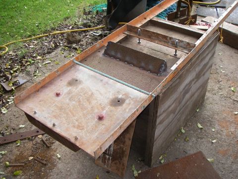
The light-weight shutter does not need an acrow to support it and so it is MUCH easier to install and a joy to use. The photograph shows the general arrangement, with the device lying on its back. The studding is the light-blue rod, the upper shutter plate has the improved 'letter-box' form and a couple of 'pretend' fixing bolts are shown in the cross-piece in more or less the correct position.
The sector immediately above the excavation point has indents created by the legs of the last shutter. In use, the legs slot into these indentations and so they align very easily. The legs are held in position by the horizontal piece bolted to the sector above. This and the indentations are almost sufficient to keep the legs in alignment, but the length of studding makes absolutely certain.
Unfortunately, foresight ran out at this stage.
When we were concreting directly under the rings, the shuttering was continued ABOVE the level of the bottom of the concrete ring and the last of the concrete was fed in from above into the gap between the shutter and the curvature of the ring. The void under the ring could thus be completely filled.
When the concreting immediately under the ring had been completed, the shaft had now become octagonal rather than circular and it was now not possible to fill the void in this way as it was not possible to get concrete past the shutter. The first three sectors of the second ring were filled as far as possible in the hope that the void could be filled later by pointing it in. This has proved both difficult to achieve and largely ineffectual. Some other technique would be needed.
6: The 'Final Version'
If you don't have any good ideas of your own then pinch someone else's, or as Tom Lehrer rather more poetically put it:-
.. plagiarise, plagiarise, let no one's work ever evade your eyes ..
In Vol I of Practical Coal Mining by E. Mason, there is the following diagram:-
Which shows EXACTLY how we should arrange our shuttering so that each section can be filled completely. The scales are a little different but the principle is the same. The critical bit is the brick wrapped in brattice cloth(†). This can be removed when the concrete has set and so leaves a gap through which the concrete for the next section can be poured; aided by the lipped section of shuttering.
In our case, the brick wrapped in brattice cloth has been replaced by a piece of wood shaped to make it easier to remove, then bolted to the bottom shuttering panel. The upper (plain) shuttering panel has been replaced by a lipped version as similar to the one illustrated above.
__________
(†) Brattice cloth was widely used in coal mines, fixed onto wooden frameworks to control ventilation air-flow. It was also useful, general purpose STUFF
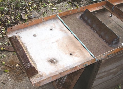
The photograph above shows the lower shuttering panel resting (inverted) on the shutter frame. In use, of course the bit of wood is not visible.
7: The Result.
 (1) |
 (2) |
Thumbnail (1). Shows the lightweight shutter in position, bolted to the segment above. In practice, this works quite well, but it is sometimes necessary to hold the frame legs together with a length of 8mm studding. The front of the shuttering is in two sections. In use, first the reinforcing is set in position, then the bottom panel slid into position from above and held in place by small wooden wedges acting between the panel and the side bolts. Concrete is then added up to the top of the first panel.
The 'letter-box' panel is then added and wedged into place. Initially this overlaps with the bottom panel, but as concrete is added, it can be gradually raised by a judicious combination of alternately hammering the panel up and tapping the wedges down. this keeps the space available to add the concrete as large as possible for as long as possible. Finally the 'letter-box' is fixed in position at full height and the last doses of concrete added and rammed home with a specialised rammer (or a bit of broom handle).
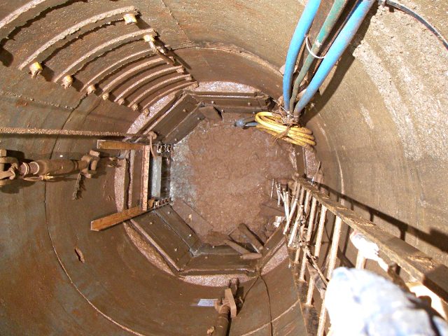
Thumbnail (2). Shows the bottom of the shaft from above with the lightweight shutter in position on the left of the photograph. Also visible are:-
- The blue surface water drainage pipes. With any luck these will be acting as hydraulic mining monitors and be quietly digging down the rift feature for us while we continue with the concreting.
- The guide rope, on the left of the photograph
- The yellow washwater hose. This is used for cleaning up the area before and after laying the concrete.
- One and a bit of the bottle jacks that tension the support strapping for the shaft.
- The electron ladder extension to the fixed ladder. We do need more fixed ladder, I've got as far as finding the steel strip and the welding jigs.
To see all this detail, click on the thumbnail to view the enlarged version.
 |
 |
Created: Tue Jul 19 20:18:22 2011
Updated: Wed Aug 14 17:39:06 2013
Revised: